So, now that we’ve been reminded a bit about Terraform’s data types and loops, it’s time to start building something real.
The first thing we will deploy with Terraform is the AWS Elastic Kubernetes Service cluster and all the resources associated with it because now it is done with AWS CDK, and in addition to other problems with CDK, we are forced to have EKS 1.26 because 1.27 is not yet supported in CDK, while Terraform has it.
In this, the first part, we will see how to create AWS resources for networking, in the second – the creation of an EKS cluster with Terraform,, and in the following – the installation of EKS controllers such as Karpenter, AWS Load Balancer Controller, and so on.
All parts:
- Terraform: building EKS, part 1 – VPC, Subnets and Endpoints (this)
- Terraform: building EKS, part 2 – an EKS cluster, WorkerNodes, and IAM
- Terraform: building EKS, part 3 – Karpenter installation
- Terraform: building EKS, part 4 – installing controllers
Contents
Planning
In general, what needs to be done is to describe the deployment of the EKS cluster and install various default things like controllers:
- AWS:
- VPC:
- 6 subnets – 2 private, 2 public, 2 for EKS Control Plane
- VPC Endpoints – S3, STS, DynamoDB, ECR
- EKS cluster:
- create a default NodeGroup with a
CrticalAddonsOnly=truetag and add Taints (see Kubernetes: Pods and WorkerNodes – control the placement of the Pods on the Nodes) - create a new StorageClass with the
ReclaimPolicy=Retain - add a “masters_access_role” and my IAM User as admins to the
aws-authConfigMap – “everything is just beginning” (c), so let’s skip RBAC to avoid complications
- create a default NodeGroup with a
- IAM:
- create “masters_access_role” with the
eks:DescribeClusterpolicy foraws eks update-kubeconfigto add users later - add OIDC Provider for the cluster
- create “masters_access_role” with the
- VPC:
- in the EKS cluster:
-
- install EKS EBS CSI Add-on
- install ExternalDNS controller
- install AWS Load Balancer Controller
- add SecretStore CSI Driver and ASCP
- install Metrics Server
- install Karpenter
- add Vertical Pod Autoscaler and Horizontal Pod Autoscaler
-
We are going to use the Terraform modules for VPC and EKS that were created by Anton Babenko, because they already implement most of the things that we need to create.
Dev/Prod environments
Here we will use the dedicated directories approach for Dev and Prod, see, see Terraform: dynamic remote state with AWS S3 and multiple environments by directory.
So now the directories/files structure looks like this:
$ tree terraform
terraform
└── environments
    ├── dev
    │   ├── backend.tf
    │   ├── main.tf
    │   ├── outputs.tf
    │   ├── providers.tf
    │   ├── terraform.tfvars
    │   └── variables.tf
    └── prod

4 directories, 6 files
When everything is ready on the Dev env, we’ll copy it to the Prod and will update the file terraform.tfvars.
Terraform debug
In case of problems, enable the debug log through the TF_LOG variable and specify the level:
$ export TF_LOG=INFO
$ terraform apply
Preparing Terraform
Describe the AWS Provider, and set default_tags which will be added to all resources created using the provider. Then we will add additional tags of the Name type in the resources themselves.
We will authorize the provider through an IAM Role (see Authentication and Configuration) because it will be added as a “hidden root user of the EKS cluster” later, see Enabling IAM principal access to your cluster:
terraform {
  required_providers {
    aws = {
      source  = "hashicorp/aws"
      version = "~> 5.14.0"
    }
  }
}

provider "aws" {
  region  = "us-east-1"
  assume_role {
    role_arn = "arn:aws:iam::492***148:role/tf-admin"
  }
  default_tags {
    tags = {
      component = var.component
      created-by = "terraform"
      environment = var.environment
    }
  }
}
And authentication in AWS itself is done through the environment variables AWS_ACCESS_KEY_ID, AWS_SECRET_ACCESS_KEY, and AWS_REGION.
Create a backend.tf file – an S3 bucket and DynamoDB table have already been created from another project (I decided to move S3 and DynamoDB management to a separate Terraform project in a separate repository):
terraform {
  backend "s3" {
    bucket = "tf-state-backend-atlas-eks"
    key    = "dev/atlas-eks.tfstate"
    region = "us-east-1"
    dynamodb_table = "tf-state-lock-atlas-eks"
    encrypt = true
  }
}
Add the first variables:
variable "project_name" {
  description = "A project name to be used in resources"
  type        = string
  default     = "atlas-eks"
}

variable "component" {
  description = "A team using this project (backend, web, ios, data, devops)"
  type = string
}

variable "environment" {
  description = "Dev/Prod, will be used in AWS resources Name tag, and resources names"
  type        = string
}

variable "eks_version" {
  description = "Kubernetes version, will be used in AWS resources names and to specify which EKS version to create/update"
  type        = string
}
And add a terraform.tfvars file. Here we set all non-sensitive data, and sensitive will be passed data with -var or environment variables in CI/CD in the form of TF_VAR_var_name:
project_name = "atlas-eks"
environment        = "dev"
component          = "devops"
eks_version        = "1.27"
vpc_cidr           = "10.1.0.0/16"
With the project_name, environment, and eks_version, we can later create a name as:
locals {
  # create a name like 'atlas-eks-dev-1-27'
  env_name = "${var.project_name}-${var.environment}-${replace(var.eks_version, ".", "-")}"
}
Let’s go.
Creating an AWS VPC with Terraform
For the VPC, we will need Availability Zones, and we will get them by using the data "aws_availability_zones" because in the future we will most likely migrate to other AWS regions.
To create a VPC with Terraform, let’s take a module from @Anton Babenko – terraform-aws-vpc.
VPC Subnets
For the module, we will need to pass public and private subnets as CIDR blocks.
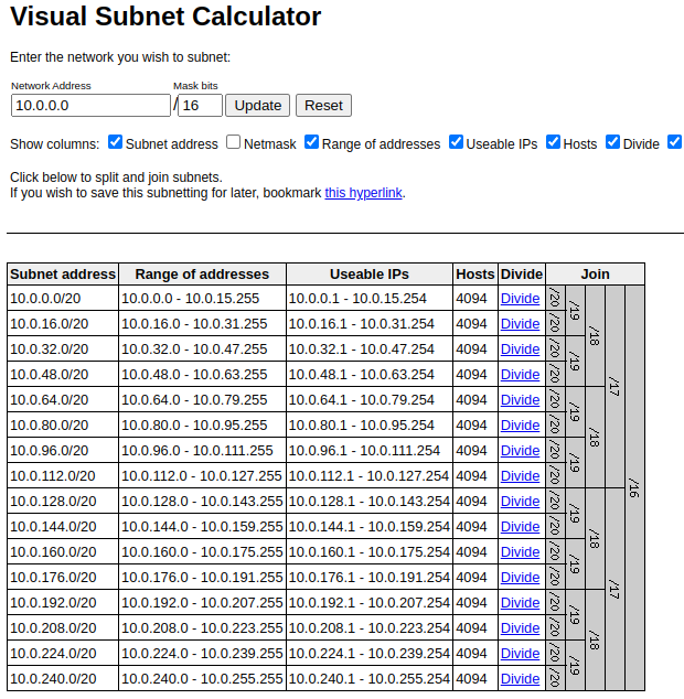
There is an option to calculate them yourself and pass them through variables. To do so, you can use either IP Calculator or Visual Subnet Calculator.
Both tools are quite interesting because the IP Calculator excellent displays information including its binary form, and the Visual Subnet Calculator shows how the block is divided into smaller blocks:
Another approach is to create blocks directly in the code using the cidrsubnets function used in the terraform-aws-vpc module.
The third approach is to manage addresses through another module, for example subnets. Let’s try it (in fact, under the hood, it also uses the same cidrsubnets function).
Basically, all you need to do here is to set a number of bits for subnets. The more bits you specify, the greater is the “offset” on the mask, and the less will be allocated to the subnet, that is:
- subnet-1: 8 біт
- subnet-2: 4 біт
If a VPC CIDR is /16, it will look like this:
11111111.11111111.00000000.00000000
Accordingly, for the subnet-1 its mask will be 16+8, i.e. 11111111.11111111.11111111.00000000 – /24 (24 bits are “busy”, the last 8 bits are “free”), and for the subnet-2 it will be 16+4, i.e. 11111111.11111111.11110000.00000000 – /20, see the table in IP V4 subnet masks.
Then in the case of 11111111.11111111.11111111.11111111.00000000 we have the last octet free for addressing, i.e. 256 addresses, and in the 11111111.11111111.11110000.00000000 – 4096 addresses.
This time, I decided to move away from the practice of creating separate VPCs for each service/component of a project because in the future it firstly complicates management due to the need to create additional VPC Peerings and carefully think through address blocks to avoid overlapping addresses, and secondly, VPC Peerings will cost extra money for traffic between them.
So, there will be a separate VPC for Dev, and a separate one for Prod, so you need to set up a large pool of addresses right away.
To do so, we’ll make the VPC itself /16, and inside it, we’ll “cut” the subnets into /20 – private ones will have EKS Pods and some AWS internal services like Lambda functions, and public ones will have NAT Gateways, Application Load Balancers, and whatever else will appear later.
Also, we need to create dedicated subnets for the Kubernetes Control Plane.
For the VPC parameters, we’ll create a single variable with the object type because there we’ll be storing not only CIDRs but also other parameters with different types:
variable "vpc_params" {
  type        = object({
    vpc_cidr  = string
  })
}
Add values to the terraform.tfvars:
...
vpc_params  = {
  vpc_cidr  = "10.1.0.0/16"
}
And in the main.tf describe how to get the Availability Zones list and create a local variable env_name for the tags:
data "aws_availability_zones" "available" {
  state = "available"
}

locals {
  # create a name like 'atlas-eks-dev-1-27'
  env_name = "${var.project_name}-${var.environment}-${replace(var.eks_version, ".", "-")}"
}
The VPC and related resources are placed in a separate file vpc.tf, where we describe the subnets module itself with six subnets – 2 public, 2 private, and 2 small ones – for EKS Control Plane:
module "subnet_addrs" {
  source  = "hashicorp/subnets/cidr"
  version = "1.0.0"

  base_cidr_block = var.vpc_params.vpc_cidr
  networks = [
    {
      name     = "public-1"
      new_bits = 4
    },
    {
      name     = "public-2"
      new_bits = 4
    },
    {
      name     = "private-1"
      new_bits = 4
    },
    {
      name     = "private-2"
      new_bits = 4
    },
    {
      name     = "intra-1"
      new_bits = 8
    },
    {
      name     = "intra-2"
      new_bits = 8
    },
  ]
}
Let’s see how it works, either with terraform apply, or let’s add outputs.
In the outputs.tf file, add the VPC CIDR, the env_name variable, and the subnets.
The subnets module has two types of outputs – the network_cidr_blocks returns a map with the names of networks in the keys, and networks returns a list (see Terraform: introduction to data types – primitives and complex).
We need to use the network_cidr_blocks because we have the type of subnet in the names – “private” or “public”.
So create the following outputs:
output "env_name" {
  value = local.env_name
}

output "vpc_cidr" {
  value = var.vpc_params.vpc_cidr
}

output "vpc_public_subnets" {
  value = [module.subnet_addrs.network_cidr_blocks["public-1"], module.subnet_addrs.network_cidr_blocks["public-2"]]
}

output "vpc_private_subnets" {
  value = [module.subnet_addrs.network_cidr_blocks["private-1"], module.subnet_addrs.network_cidr_blocks["private-2"]]
}

output "vpc_intra_subnets" {
  value = [module.subnet_addrs.network_cidr_blocks["intra-1"], module.subnet_addrs.network_cidr_blocks["intra-2"]]
}
In the VPC module, in the vpc_public_subnets, vpc_private_subnets, and intra_subnets parameters, pass a map with two elements – for each subnet of the corresponding type.
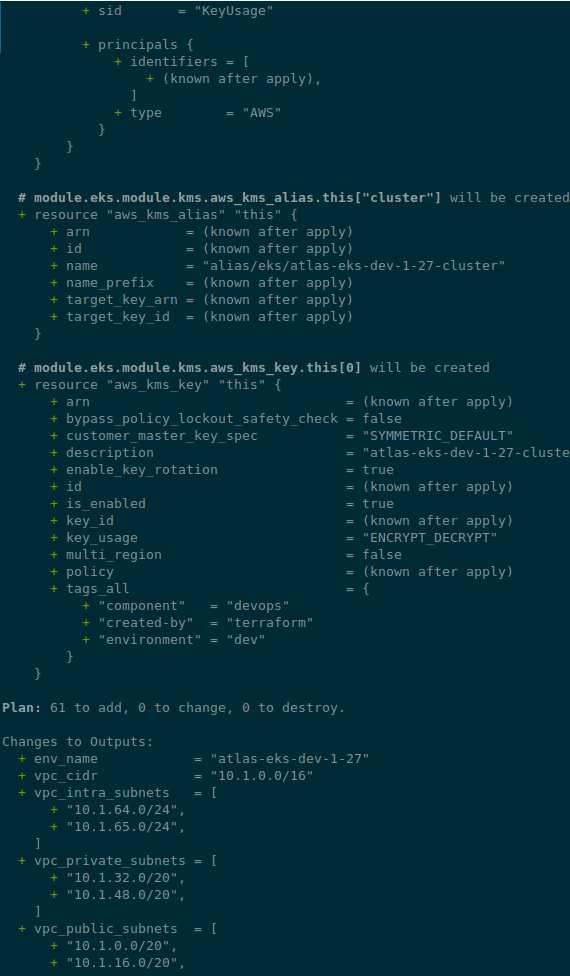
Check with terraform plan:
...
Changes to Outputs:
  + env_name            = "atlas-eks-dev-1-27"
  + vpc_cidr            = "10.1.0.0/16"
  + vpc_intra_subnets   = [
      + "10.1.64.0/24",
      + "10.1.65.0/24",
    ]
  + vpc_private_subnets = [
      + "10.1.32.0/20",
      + "10.1.48.0/20",
    ]
  + vpc_public_subnets  = [
      + "10.1.0.0/20",
      + "10.1.16.0/20",
    ]
Looks okay?
Let’s move on to the VPC itself.
Terraform VPC module
The module has quite a few inputs for configuration, and there is a good example of how it can be used – examples/complete/main.tf.
What we might need here:
putin_khuylo: the must-have option with the obvious valuetruepublic_subnet_names,private_subnet_names, andintra_subnet_names: you can set your own subnet names – but the default names are quite convenient, so I don’t see any reason to change them (seemain.tf)enable_nat_gateway,one_nat_gateway_per_azorsingle_nat_gateway: parameters for NAT Gateway – actually, we will use the default model, with a dedicated NAT GW for each private network, but we will add the ability to change it in the future (although it is possible to build a cluster without NAT GW at all, see Private cluster requirements)enable_vpn_gateway: not yet, but we will add it for the futureenable_flow_log: very useful (see AWS: Grafana Loki, InterZone traffic in AWS, and Kubernetes nodeAffinity), but it adds extra costs, so let’s add but not enable yet
Add parameters to our vpc_params variable:
variable "vpc_params" {
  type = object({
    vpc_cidr               = string
    enable_nat_gateway     = bool
    one_nat_gateway_per_az = bool
    single_nat_gateway     = bool
    enable_vpn_gateway     = bool
    enable_flow_log        = bool
  })
}
And add values to the tfvars:
...
vpc_params = {
  vpc_cidr               = "10.1.0.0/16"
  enable_nat_gateway     = true
  one_nat_gateway_per_az = true
  single_nat_gateway     = false
  enable_vpn_gateway     = false
  enable_flow_log        = false
}
Regarding tags: you can specify tags from the vpc_tags and/or private/public_subnet_tags inputs.
You can also add tags through tags of the VPC resource itself – then they will be added to all resources of this VPC (plus default_tags from the AWS provider)
Next, describe the VPC itself in the vpc.tf:
...
module "vpc" {
  source  = "terraform-aws-modules/vpc/aws"
  version = "~> 5.1.1"

  name = "${local.env_name}-vpc"
  cidr = var.vpc_params.vpc_cidr

  azs = data.aws_availability_zones.available.names

  putin_khuylo = true

  public_subnets  = [module.subnet_addrs.network_cidr_blocks["public-1"], module.subnet_addrs.network_cidr_blocks["public-2"]]
  private_subnets = [module.subnet_addrs.network_cidr_blocks["private-1"], module.subnet_addrs.network_cidr_blocks["private-2"]]
  intra_subnets   = [module.subnet_addrs.network_cidr_blocks["intra-1"], module.subnet_addrs.network_cidr_blocks["intra-2"]]

  enable_nat_gateway = var.vpc_params.enable_nat_gateway
  enable_vpn_gateway = var.vpc_params.enable_vpn_gateway

  enable_flow_log = var.vpc_params.enable_flow_log
}
And check again with terraform plan:
If it looks OK, deploy it:
$ terraform apply
...
Apply complete! Resources: 23 added, 0 changed, 0 destroyed.

Outputs:

env_name = "atlas-eks-dev-1-27"
vpc_cidr = "10.1.0.0/16"
vpc_intra_subnets = [
  "10.1.64.0/24",
  "10.1.65.0/24",
]
vpc_private_subnets = [
  "10.1.32.0/20",
  "10.1.48.0/20",
]
vpc_public_subnets = [
  "10.1.0.0/20",
  "10.1.16.0/20",
]
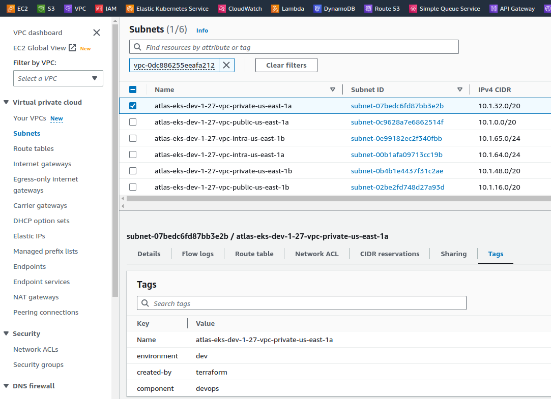
And check the subnets:
Adding VPC Endpoints
Lastly, for VPCs, we need to configure VPC Endpoints.
This is a must-have feature from both a security and infrastructure cost perspective because in both cases your traffic will go inside the Amazon network instead of travelling across the Internet to external AWS endpoints like s3.us-east-1.amazonaws.com.
The VPC Endpoint will create a Route Table with routes to the appropriate endpoint within the VPC (in the case of Gateway Endpoint), or create an Elastic Network Interface and change the VPC DNS settings (in the case of Interface Endpoints), and all traffic will go inside the AWS network. See also VPC Interface Endpoint vs Gateway Endpoint in AWS.
Endpoints can be created using the internal module vpc-endpoints, which is included in the VPC module itself.
An example of endpoints is in the same examples/complete/main.tf file or on the submodule page, and we need them all except ECS and AWS RDS – in my particular case, there is no RDS on the project, but there is DynamoDB.
We’ll also add an endpoint for the AWS STS, but unlike the others, for traffic to go through this endpoint, services must use the AWS STS Regionalized endpoints. This usually can be set in Helm charts through values or for ServiceAccount via the annotation eks.amazonaws.com/sts-regional-endpoints: "true".
Keep in mind that using Interface Endpoints costs money because AWS PrivateLink is used under the hood, and Gateway Endpoints are free, but only available for S3 and DynamoDB.
However, this is still much more cost-effective than send traffic via NAT Gateways, where traffic costs 4.5 cents per gigabyte (plus the cost per hour of the gateway itself), while through the Endpoint Interface we will pay only 1 cent per gigabyte of traffic. See Cost Optimization: Amazon Virtual Private Cloud and VPC Endpoint Interface.
In the module, we can also create an IAM Policy for endpoints. But since we will have only Kubernetes with its Pods in this VPC, I don’t see any point in additional policies yet. In addition, you can add a Security Group for Interface Endpoints.
The endpoints for STS and ECR will be of the Interface type, so we pass the IDs of private networks to them, and for S3 and DynamoDB, we pass the IDs of routing tables because they will be Gateway Endpoints.
We make S3 and DynamoDB endpoints of the Gateway type because they are free, and the others will be the Interface type.
So, add the endpoints module to our vpc.tf:
...
module "endpoints" {
  source  = "terraform-aws-modules/vpc/aws//modules/vpc-endpoints"
  version = "~> 5.1.1"

  vpc_id = module.vpc.vpc_id

  create_security_group = true

  security_group_description = "VPC endpoint security group"
  security_group_rules = {
    ingress_https = {
      description = "HTTPS from VPC"
      cidr_blocks = [module.vpc.vpc_cidr_block]
    }
  }

  endpoints = {
    dynamodb = {
      service         = "dynamodb"
      service_type    = "Gateway"
      route_table_ids = flatten([module.vpc.intra_route_table_ids, module.vpc.private_route_table_ids, module.vpc.public_route_table_ids])
      tags = { Name = "${local.env_name}-vpc-ddb-ep" }
    }
    s3 = {
      service         = "s3"
      service_type    = "Gateway"
      route_table_ids = flatten([module.vpc.intra_route_table_ids, module.vpc.private_route_table_ids, module.vpc.public_route_table_ids])
      tags = { Name = "${local.env_name}-vpc-s3-ep" }
    },
    sts = {
      service             = "sts"
      private_dns_enabled = true
      subnet_ids          = module.vpc.private_subnets
      tags = { Name = "${local.env_name}-vpc-sts-ep" }
    },
    ecr_api = {
      service             = "ecr.api"
      private_dns_enabled = true
      subnet_ids          = module.vpc.private_subnets
      tags = { Name = "${local.env_name}-vpc-ecr-api-ep" }
    },
    ecr_dkr = {
      service             = "ecr.dkr"
      private_dns_enabled = true
      subnet_ids          = module.vpc.private_subnets
      tags = { Name = "${local.env_name}-vpc-ecr-dkr-ep" }
    }
  }
}
In the source we specify a path with two slashes because:
The double slash (
//) is intentional and required. Terraform uses it to specify subfolders within a Git repo
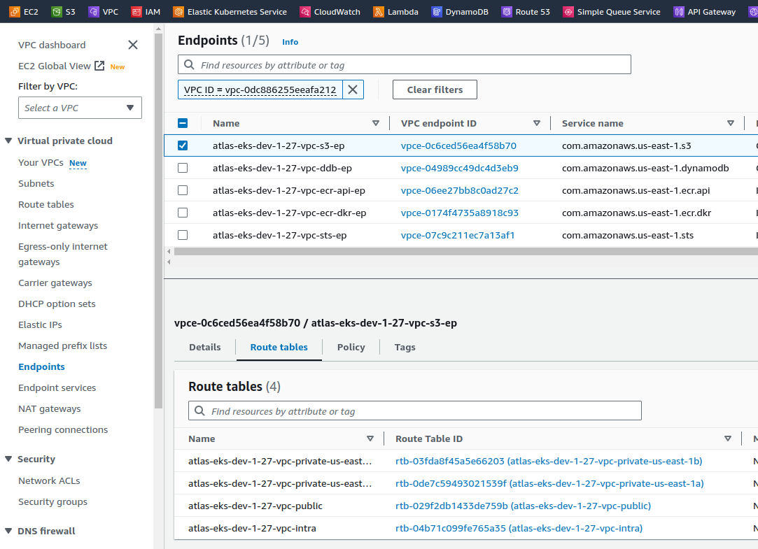
Run terraform init again, check with the plan, deploy, and check the endpoints in the AWS Console:
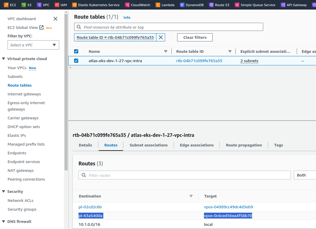
And check the routing tables – where will they route the traffic? For example, the atlas-eks-dev-1-27-vpc-intra Route Table has three routes:
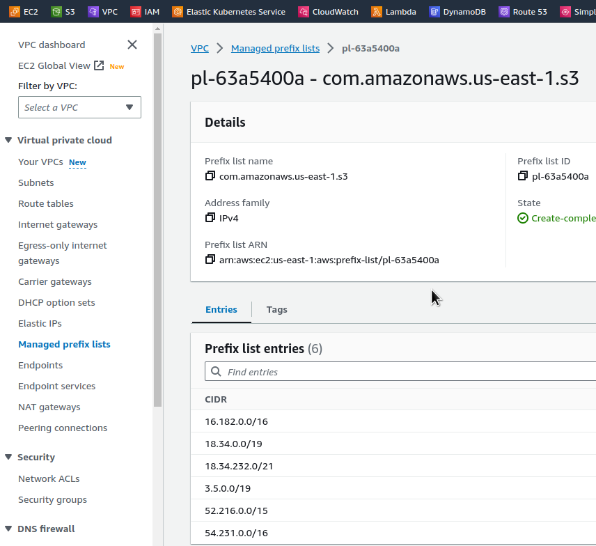
The pl-63a5400a prefix list will send traffic through the vpce-0c6ced56ea4f58b70 endpoint, i.e. atlas-eks-dev-1-27-vpc-s3-ep.
Content of the pl-63a5400a:
And if we do a dig to the s3.us-east-1.amazonaws.com address, we will get the following IP addresses:
$ dig s3.us-east-1.amazonaws.com +short
52.217.161.80
52.217.225.240
54.231.195.64
52.216.222.32
16.182.66.224
52.217.161.168
52.217.140.224
52.217.236.168
The addresses here are all from the pl-63a5400a list, i.e. all requests inside the VPC to the URL s3.us-east-1.amazonaws.com will be executed through our S3 Endpoint VPC.
Looking ahead, when the EKS cluster was already running, I checked how the Interface Endpoints worked, for example, for STS.
From a work laptop in the office:
18:46:34 [setevoy@setevoy-wrk-laptop ~]  $ dig sts.us-east-1.amazonaws.com +short
209.54.177.185
And from a Kubernetes Pod on the private network of our VPC:
root@pod:/# dig sts.us-east-1.amazonaws.com +short
10.1.55.230
10.1.33.247
So, looks like we finished here, and it’s time to move on to the next task – creating the cluster itself and its WorkerNodes.
