It’s difficult to describe in one post what thousands of books have been written about in a thousand pages, but today we’ll try to quickly review the basics of how hosts communicate on a network.
First, let’s talk about the OSI and TCP/IP models, then about packet structure and connection establishment, and finally, we’ll look under the hood of Linux and take a look at sockets and the Linux TCP stack.
We will mainly focus on TCP, because that’s what we deal with most often.
Contents
What is: The TCP/IP
So, the “TCP/IP” term includes two main concepts:
- First, it is a stack of communication protocols (standards, sets of rules) – TCP (Transmission Control Protocol), and IP (Internet Protocol): they describe how connections are established between hosts and services on the Internet. These protocols are standardized and described in the relevant RFCs (TCP – RFC: 793, IP – RFC: 791)
- in addition, TCP/IP is a communication model that includes several layers – similar to the OSI model (and which is also described in the Informational RFC – RFC 1180)
The general OSI model
The OSI model (Open Systems Interconnection model) was developed and standardized by ISO (International Organization for Standardization) in 1984 – see ISO/IEC 35.100.
So, the main idea of the model is that any connection in the network goes through several levels of communication, where each level is responsible only for its own task and does not have access to the logic of other levels – this is called the Layer isolation.
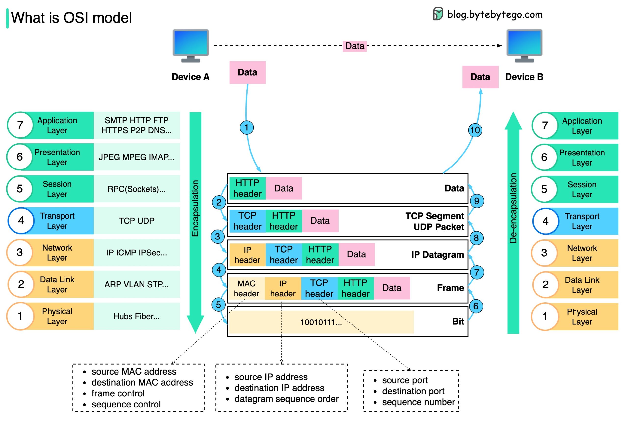
When transmitting data between layers, the Encapsulation principle is used – each layer “wraps” the data packet in its own “wrapper” – adds its own headers to the packet without changing the content of the previous layer. Thus, it encapsulates the logic of that particular layer to provide the layer isolation.
In a very simplified way, the process can be represented as follows:
- when our browser generates an HTTP request, it happens at the topmost level, the Application layer
- this request is transmitted below, to the Transport layer, where the data from the browser is encapsulated: the data from the Application layer has added a headers from the Transport layer – the TCP headers
- then, even lower, an IP header is added to the Network layer, which indicates the address of the sender and recipient
- and finally, an Ethernet frame is formed on the Link layer, which is transmitted through the Physical layer
On the receiving side (for example, an EC2 instance with NGINX), everything happens in the opposite direction – decapsulation: each layer removes its wrapper and passes the rest of the data received to the higher layer.
There is a good diagram in OSI Model Explained (although here the HTTP header is displayed opposite the Session layer – but this happens on the Application layer):
PDU (Protocol Data Unit)
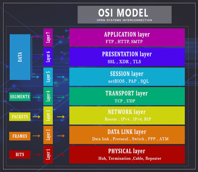
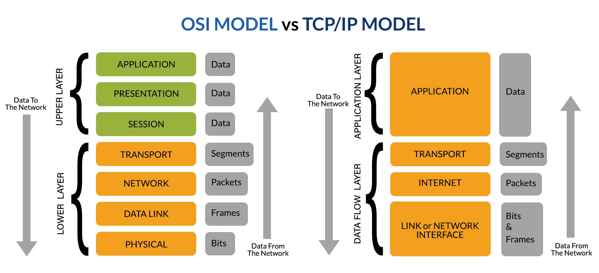
In addition, when we say “packet” when referring to data, technically, at each level of the OSI model, this data is called differently, and the common name for it is PDU (Protocol Data Unit):
Note: although this diagram also has inaccuracies, for example, SQL is a query language for the Application layer
I.e:
- Application, Presentation, Session layers are just Data
- Transport layer (layer 4) is Segment (in TCP) or Datagram (UDP)
- Network layer – Packet (for example, an IP packet that can contain a TCP segment)
- Data Link layer – operates Frames
- Physical layer – these are already bits, 0 and 1
The process of data transfer from the browser to the web server with TLS
Let’s take a closer look at how the data transfer process works:
- Layer 7 – Application layer:
- the browser needs to send data – the payload
- it operates on the Application layer, and an HTTP request is generated with HTTP headers (authentication, caching, the request itself to the desired resource – URI, and where the request goes – URL)
- here an HTTP session is established – through cookies, JWT token, URL parameters, etc.
- the generated data is transferred to the Presentation Layer
- Layer 6 – Presentation Layer:
- if encryption is used, SSL/TLS libraries are connected here and encrypt the data
- TLS headers are added
- if necessary, data conversion is performed, for example, character encoding (ASCII, UTF-8)
- Layer 5 – Session Layer:
- this is where the TLS handshake process takes place – setting up encryption methods and keys (cool material on this topic is The Illustrated TLS 1.2 Connection)
- creates a TLS session between the client and the server
- Layer 4 – Transport Layer:
- TCP-segment is formed here (or the datagram for UDP, but here we are considering a browser and HTTP, so TCP):
- TCP headers are added to the data from higher layers (for example, the browser) – Source port, Destination port, Sequence number – a packet number (see Multiplexing and Demultiplexing in Transport Layer)
- TCP flags are set –
ACK, etc. the - size of the TCP segment is limited by MSS (Maximum Segment Size) – we will look further
- Layer 3 – Network Layer:
- here, IP headers are added to the TCP segment – where the packet is sent from (source IP), where it goes (destination IP), and the IP packet is formed
- data on TTL (Time To Live) of the pact, packet checksum is added to check by the recipient – whether the packet arrived intact
- IP address size – 32 bits in IPv4, and 128 bits in IPv6
- the type of data transmission depends on the IP address – unicast (to one addressee),
- multicast (to several addressees), there is broadcast – to all hosts in a given network
- at the same level ICMP works to exchange information about the network status and errors on the
- Network layer ICMP packets can be created automatically in case of problems at the routing level
- but can also be generated on the Application layer, for example, by
pingortracerouteutilities
- Layer 2 – Data Link Layer:
- Ethernet, Wi-Fi – network card drivers generate a frame, adding the MAC address of the sender and receiver and their own packet integrity check – CRC (cyclic redundancy check)
- MAC addresses are determined using the ARP (Address Resolution Protocol) protocol
- Layer 1 – Physical Layer:
- physical connection, electrical or optical signals
DNS in the OSI model
Let’s look at DNS separately:
- Layer 7 – Application layer:
- browser needs to send a request to “google.com”
- browser executes
getaddrinfo() orgethostbyname() (deprecated) from theglibclibraryglibcchecks the parameters of/etc/nsswitch.conf:- if necessary, perform an external DNS query (for example, if there is no entry in
/etc/hosts) – checks the parameters in/etc/resolv/conf - DNS query is generated, UPD or TCP socket is opened
- if necessary, perform an external DNS query (for example, if there is no entry in
- Layer 4 – Transport Layer:
- at the transport layer, a header with destination port 53 is added to the PDU (TCP segment or UDP datagram) (usually UDP, but can be TCP – if the response is larger than 512 bytes or DNS-over-TCP, DoT mode is enabled – see RFC 7766)
- Layer 3 – Network Layer:
- IP headers are added to the packet – where exactly to send the request
- Layer 2 – Data Link Layer and Layer 1 – Physical Layer: data transmission
OSI ISO model vs TCP/IP model
The TCP/IP (or Internet Protocol Suite) model was developed in the 1970s, before the advent of OSI, and formed the basis of the Internet (and its predecessor, the ARPANET).
The OSI ISO and TCP/IP models are designed to unify communication between devices, but have key differences:
- OSI describes 7 layers, while TCP/IP – 4 Application
- Layer in TCP/IP includes Application, Presentation and Session layers of the OSI model
- and Network Access Layer in TCP/IP includes Data Link and Physical layers of the OSI model (sometimes called Link Layer)
- The OSI model is more of an “academic model” that is used to explain the principles of networking, and TCP/IP is an “application model” on which communication on the Internet is actually built
The main difference is that:
- the TCP/IP model was created to describe the existing protocols (TCP, IP, FTP, SMTP, etc.) that were used in the ARPANET – that is, first the technology, and then its description in the form of a model.
- The OSI model, on the other hand, is more of a theoretical model that was first described (“how it should be”), and then new protocols were added to this model.
A good illustration of the model layers can be found in A Refresher Course on OSI & TCP/IP:
 TCP headers and payload
Okay – with the general scheme of data transfer understood, let’s take a closer look at what is transmitted in TCP/IP and how it is transmitted.
Since we have already mentioned TCP headers, let’s start with them.
The TCP header has the same structure regardless of whether it is transmitted within IPv4 or IPv6. It has a minimum size of 20 bytes and a maximum size of 60 bytes, due to the use of the Options field.
IPv4 headers have a variable length – from 20 to 60 bytes, but IPv6 headers are fixed at 40 bytes.
MTU, MSS and TCP Payload
The maximum amount of data that can be transmitted in a single IP packet and TCP segment, and depends on the size of the Ethernet frame, MTU (Maximum Transmission Unit), which is set to 1500 bytes by default:
$ ifconfig wlan0 | grep -i MTU
wlan0: flags=4099<UP,BROADCAST,MULTICAST> mtu 1500
The space for TCP and IP headers is subtracted from these 1500 bytes, and as a result, we’ll get the MSS (Maximum Segment Size) – the maximum size of useful data in a TCP segment:
MSS = (MTU) - (IP header) - (TCP header)
    = 1500 - 20 - 20
    = 1460 байт
The MSS is declared during the TCP handshake via the TCP option MSS in the SYN packet, and both parties agree on a value that allows the sender to take this size into account to avoid IP fragmentation.
If the TCP payload exceeds the MSS, the TCP stack performs segmentation, i.e. splits this stream into several separate TCP segments.
For example, a browser sends a POST request of 3000 bytes – then TCP will divide this request into:
- segment 1 with a data size of 1460 bytes
- segment 2 with a data size of 1460 bytes
- segment 3 with 80 bytes
In the case of TCP segmentation, each packet will have its own headers, and its Sequence Number will indicate the position of the first byte of data in this segment in the overall data stream. The payload size of each segment will not exceed the MSS.
IP fragmentation is an exceptional situation that occurs only if a TCP segment (or other IP packet) has already exceeded the MTU, and ideally should not occur.
The structure of TCP headers
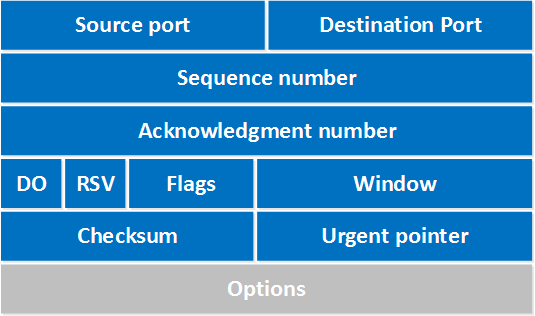
So, after receiving data from the Application layer, a TCP segment is formed, to which a set of TCP headers is added:
Note: from now on, I will use the word “flags” rather than “checkboxes”, because in the context of TCP it sounds more correct
Here:
- Source port: a 16-bit field specifying the source port
- Destination port: a 16-bit field that indicates the destination port
- Sequence number: a 32-bit field that indicates the first byte of data (payload) of each TCP segment
- Acknowledgment number: a 32-bit field transmitted by the receiver to request the next TCP segment – this will be Sequence Number + 1
- DO (data offset): a 4-bit field that indicates where the TCP header ends and the data (payload) begins
- RSV (reserved field): 3 bits, not used, and always empty
- Flags: 9 bits, also called “control bits” – used to transmit flags that control connection establishment, data transfer and connection closure
- closureURG: urgent pointer – if the flag is set, the segment has urgent data that can be transmitted on the side of the recipient operating system by a separate system call bypassing the general TCP buffer (see TCP – Urgent pointer field)
- does not affect the routing or delivery of the packet by the network and is used only locally by the kernel stack of the recipient operating system
- ACK: acknowledgment of receipt of the segment
- PSH: push function – transmit data immediately, without waiting for the TCP buffer to be filled
- RST: reset – force closure of the connection in case of errors
- SYN: start of connection (in TCP 3-way handshake, we will see further), sets the Initial Sequence Number – see below
- FIN: normal closure of the connection, sent by both the client and the server
- closureURG: urgent pointer – if the flag is set, the segment has urgent data that can be transmitted on the side of the recipient operating system by a separate system call bypassing the general TCP buffer (see TCP – Urgent pointer field)
- Window: 16 bits, indicates the maximum number of bytes that the sender (both client and server) can send without waiting for the next
ACKfrom the server (server-side kernel TCP buffer control) - Checksum: 16 bits, a checksum of the TCP header + data, used to check if the segment is not damaged during transmission
- Urgent pointer: 16 bits, if
URGis set, it indicates where the urgent data ends - Options: 0 – 320 bits, used to transmit MSS, timestamps, etc.
Sequence Number
This is a rather interesting topic, which, perhaps, makes sense to discuss separately.
TCP is a streaming protocol that transmits a sequence of bytes, not individual messages.
When transmitting data in a TCP session:
- the client sends a
SYNwith an Initial Sequence Number, which is initially set as a random number, for example, 100000 - the server responds with
SYN-ACK, confirming receipt of the connection request(SYN),- and indicates 100001 in the Acknowledgment Number field
- then, at the beginning of the transmission of the first data segment, the client will indicate Sequence Number 100001 in the first segment, and 101461 in the next segment (with MSS 1460 bytes)
That is, each subsequent segment increases the Sequence Number by the length of the payload.
View TCP headers in Wireshark
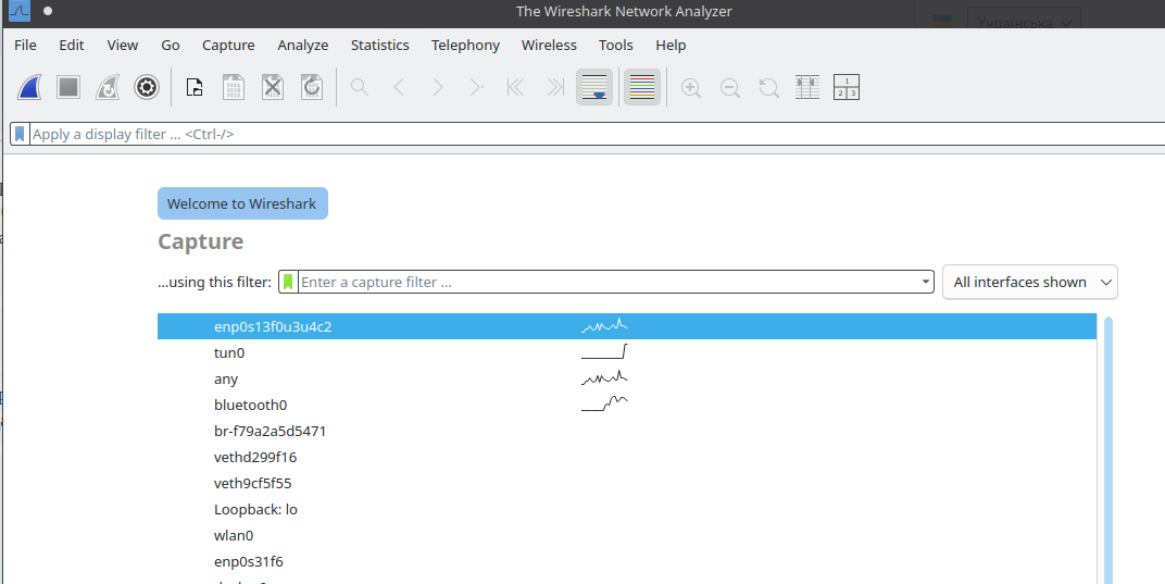
The easiest way is with wireshark (or wireshark-qt).
Run as root, select the interface:
For example, to see traffic to RTFM.co.ua blog – find the IP:
$ dig rtfm.co.ua +short
104.26.3.188
104.26.2.188
172.67.68.115
Setting the filter:
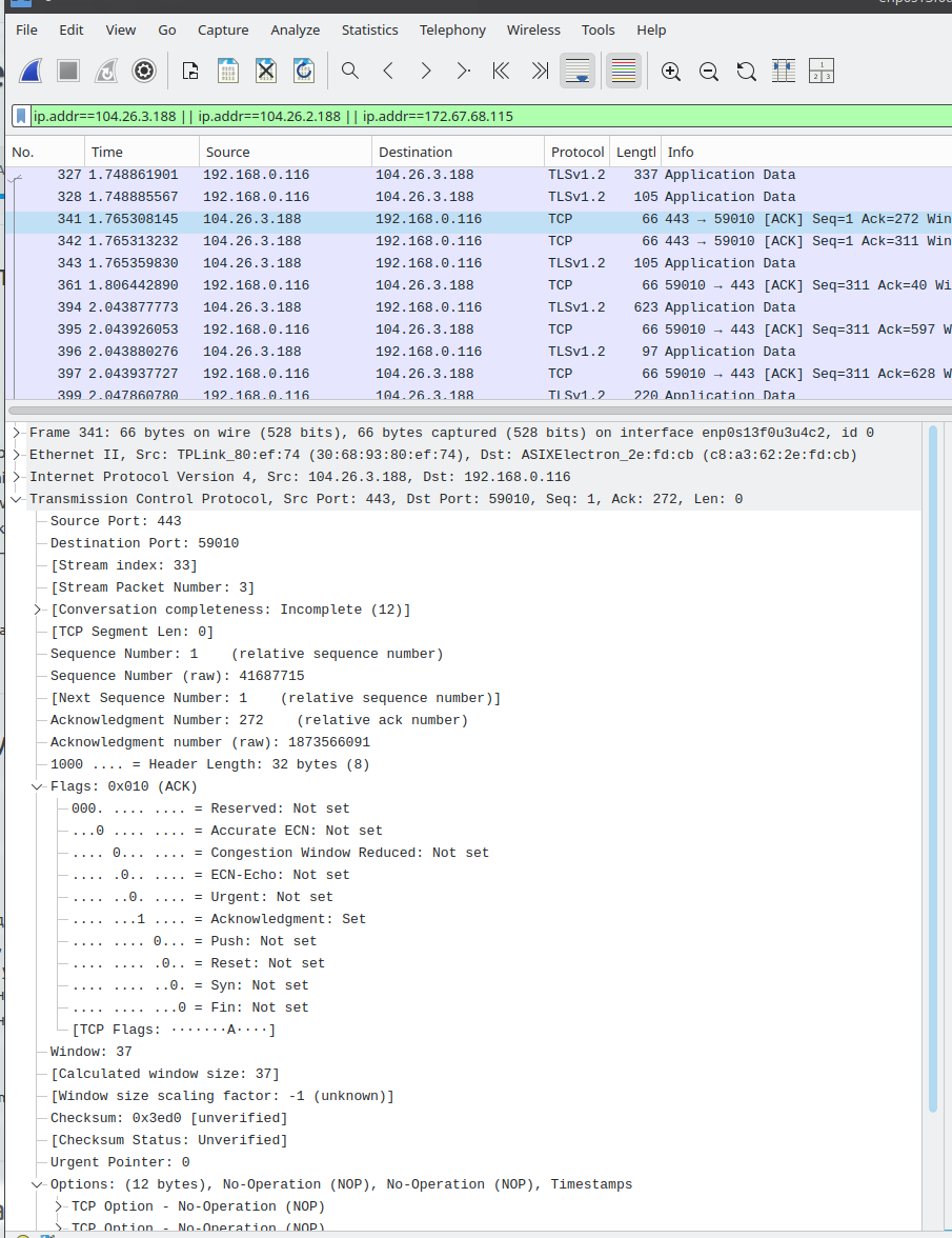
ip.addr==104.26.3.188 || ip.addr==104.26.2.188 || ip.addr==172.67.68.115
And get the data:
TCP connection
With the TCP headers out of the way, let’s take a look at how a TCP connection is established.
So, TCP is a connection-oriented protocol (i.e., it requires a session to be established before data can be transferred) that provides data delivery, flow control, and error detection during transmission.
Unlike UDP, with TCP we are either guaranteed to transfer data, or an error will be detected and the connection will be disconnected.
TCP handshake
As with TLS, the establishment of a TCP connection follows the standard 3-way handshake process.
For TLS, see What is: SSL/TLS in detail (in rus).
The TCP handshake consists of three stages (hence the name“3-way handshake”):
SYN: the client sends a packet with theSYNflag, indicating its Initial Sequence NumberSYN-ACK: the server responds with aSYNandACKpacket, which acknowledges- receipt of the
SYNfrom the client (by setting the Acknowledgment Number field) and - sends its own Initial Sequence Number
- receipt of the
ACK: the client sendsACK, which confirms the receipt ofSYN-ACKfrom the server
At this point, the session is considered established and data transfer begins.
Closing the session –“4-way FIN handshake“:
FIN: the client informs the server (or vice versa) that it has finished the transfer and is ready to close the sessionACKfrom the server: the server confirms receipt of theFINFINfrom the server: the server informs that it is also ready to close the sessionACKfrom the client: the client responds with the finalACK, confirming receipt of theFINfrom the server
After that, the connection is completely closed.
Analyzing a session with Wireshark
You can write directly to Wireshark, or you can create a file first and then analyze it.
Run tcpdump:
$ sudo tcpdump host 104.26.3.188 or host 104.26.2.188 or host 172.67.68.115 -w tcp.pcap
In another window, make a request to RTFM:
$ curl https://rtfm.co.ua
Open the generated dump in Wireshark:
$ sudo wireshark tcp.pcap
And we get all the packets that were transmitted:
This is where we first see the 3-way handshake – the beginning of the connection:
SYN(client 50556 => server 443):Seq=0, Len=0- client (192.168.0.116) opens a connection with local port 50556 to the RTFM server on 172.67.68.115 and port 443
SYN, ACK(443 → 50556):Seq=0 Ack=1, Len=0- response from the server 172.67.68.115 that it has acknowledged receipt of
SYNfrom the client 192.168.0.116 (`ACK’ flag), and sets itsSYNflagwith Initial Sequence Number, setting the starting point for its data stream
ACK(50556 → 443):Seq=1 Ack=1, Len=0- Client acknowledges
SYNfrom the server
The fourth packet is already the beginning of data transmission – Len-1388 (in fact, this is the beginning of the TLS handshake – the next, fifth packet is TLSv1.3).
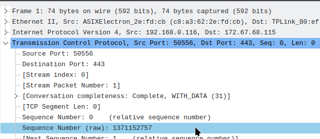
Seq=0 is exactly the Sequence Number mentioned above.
Wireshark just displays it in a form convenient for us, but we can see its real value:
Len=0 in the first three packets is zero, because this is only connection establishment, before data transmission, and the packets contain only TCP headers for connection establishment, no data.
Ack=N – acknowledgement of packet receipt.
For example:
Seq=0:- the client sends the Initial Sequence Number, which Wireshark shows us as 0
Seq=0 Ack=1 Len=0:Seq=0– the server also sets its Initial Sequence NumberAck=1– the server increments theSeqfrom the client by +1
Seq=1 Ack=1 Len=0:Seq=1– now the client increments its Sequence NumberAck=1– the client acknowledges receipt ofSYNfrom the server
TCP and the Linux kernel
The operating system kernel has its own system for transferring data via the TCP protocol – the TCP stack.
It is responsible for:
- opening and closing TCP sessions
- delivery control
(ACK,SEQ) - retransmission of lost packets
- recognize flags
(SYN,FIN,RST, etc.) - collecting data from several segments in the correct order
In fact, it is a set of functions in the kernel that process TCP packets.
And the TCP stack itself is part of the kernel’s networking stack, along with processing Ethernet, ARP, IP, UDP, and others.
See the documentation for kernel_flow.
Kernel buffers are the main thing you will encounter when setting up or tuning the kernel:
rmem_*: receive buffer (for incoming traffic)wmem_*: write buffer (for outgoing traffic)
The default values are set in /proc/sys/net/ipv4/tcp_rmem and /proc/sys/net/ipv4/tcp_wmem, respectively.
And you can override them with sysctl:
$ sudo sysctl -w net.ipv4.tcp_rmem="4096 87380 6291456"
$ sudo sysctl -w net.ipv4.tcp_wmem="4096 65536 6291456"
The kernel also supports automatic buffer scaling – the file /proc/sys/net/ipv4/tcp_moderate_rcvbuf:
$ cat /proc/sys/net/ipv4/tcp_moderate_rcvbuf
1
1 – enabled, 0 – disabled.
The minimum Maximum segment size (MSS) is set in the file /proc/sys/net/ipv4/tcp_min_snd_mss:
$ cat /proc/sys/net/ipv4/tcp_min_snd_mss
48
48 bytes == 384 bits.
The minimum size is set to prevent sending TCP segments that are too small, which will cause unnecessary overhead and performance degradation.
The process of receiving a TCP packet by the kernel
What does the process of receiving data look like in the system?
See kernel_flow.
To simplify, then:
- Layer 2: Link layer
- Network Interface Card receives an Ethernet frame with a TCP packet
- the system kernel calls the card driver, and the driver calls the
netif_receive_skb()function and transfers the entire received frame (in theskbstructure – Socket Buffer) for processing to the network subsystem of the kernel
- Layer 3: Network layer
- the packet is passed to
ip_rcv()(IPv4) oripv6_rcv() (IPv6), where the IP header is checked to determine the protocol - if Protocol = 6 (TCP) – the packet is transferred to
tcp_v4_rcv()
- the packet is passed to
- Layer 4: Transport layer
- the
tcp_v4_rcv() function checks the checksum, finds the appropriate local socket (port), processesSEQ/ACK/FIN/RST/SYNflags, and adds the payload to the receive buffer of the socket bound to the appropriate port (for example,listen(80) for a web server) - after transferring data to the web server, the kernel generates an
ACKpacket in response - the data is transferred to the internal receive buffer of the socket, and from there it is already transferred to the userspace to the web server (if we are talking about a browser server)
- the
If you go deeper, you can use utilities like Systemtap to track system calls.
Sockets and TCP ports in Linux
To work with TCP in Linux, there is a concept ofsockets– these are endpoints that are attached to the IP:PORT pair.
A great post with diagrams is the TCP handling in Linux.
A socket is an abstraction that allows programs to read/write to the network as if it were a regular file, and is essentially a special type of file descriptor: the operating system perceives them as apipe through which data can be transferred.
Sockets can be either local or networked:
AF_INETfor IPv4 andAF_INET6for IPv6AF_UNIXorAF_LOCAL– for local work
AF_* in the name is“Address Family” because we have not only TCP/UDP sockets, but also AF_UNIX – local, AF_BLUETOOTH – Bluetooth, AF_NETLINK – Netlink, etc.
When creating a socket, its type is specified:
socket(AF_INET, SOCK_STREAM, 0); // TCP
socket(AF_INET, SOCK_DGRAM, 0); // UDP
And then the bind() function is used to bind to the IP and port.
C programming: UNIX Socket
Of course, you can do it in Python, but C programming will show us more details.
I wrote an example of how sockets work in C: sockets and an example of a client-server model (in rus, 2017, my God…).
A simple example of a local socket:
// Create a UNIX domain socket file at /tmp/mysocket.sock

#include <sys/socket.h>   // import socket(), bind() functions
#include <sys/un.h>       // import C struct sockaddr_un
#include <unistd.h>       // import close() function
#include <stdio.h>        // import input/output functions like print()
#include <string.h>       // import strings/memory functions like strlen()

// def main C function
int main() {

   // define a variable with the 'int' type
   // it will store the socket's file descriptor ID returned by the socket() function
   // a file descriptor is just an integer index into the per-process open file table
   // the actual 'file' struct exists in kernel space, user space only sees the integer
    int sockfd;

    // define a variable named 'addr' with the 'struct sockaddr_un' type
    // this structure is used to specify socket address for AF_UNIX sockets
    struct sockaddr_un addr;

    // Step 1: create socket
    // socket(domain, type, protocol)
    // AF_UNIX: UNIX domain socket
    // SOCK_STREAM: stream-oriented (like TCP)
    // '0': protocal, set to 0 as AF_UNIX + SOCK_STREAM have no protocal
    sockfd = socket(AF_UNIX, SOCK_STREAM, 0);
    if (sockfd < 0) {
        perror("socket");
        return 1;
    }

    // Step 2: set up address structure
    memset(&addr, 0, sizeof(addr));              // zero out the memory for safety
    addr.sun_family = AF_UNIX;                   // set socket family (UNIX domain)
    strcpy(addr.sun_path, "/tmp/mysocket.sock"); // set path for the socket file in the 'addr' structure

    // Step 3: remove old socket file if it exists
    // unlink removes a file; important to avoid "Address already in use" error
    unlink("/tmp/mysocket.sock");

    // Step 4: bind
    //
    // bind the socket to a local address (path in the filesystem) - bind(sockfd, addr, size_of_addr)
    // 'sockfd': socket file descriptor returned by socket()
    // '&addr': pointer to the sockaddr_un struct that contains:
    // - family (AF_UNIX)
    // - path (filesystem path to the socket file)
    // '(struct sockaddr*)': cast required because bind() expects a generic sockaddr*
    // 'sizeof(addr)': size of the sockaddr_un structure
    //
    // after this call, the socket is associated with a specific name (path),
    // so other processes can connect to it via this path.
    if (bind(sockfd, (struct sockaddr*)&addr, sizeof(addr)) < 0) {
        perror("bind");
        return 1;
    }

    printf("UNIX socket created at /tmp/mysocket.sock\n");

    // Step 5: keep socket alive for inspection
    sleep(60);

    // Step 6: cleanup
    close(sockfd);                 // close the socket file descriptor
    unlink("/tmp/mysocket.sock");  // remove the socket file from filesystem
    return 0;
}
Build with gcc:
$ gcc unix_socket.c -o unix_socket
Run:
$ ./unix_socket
UNIX socket created at /tmp/mysocket.sock
And we have an open socket:
$ file /tmp/mysocket.sock
/tmp/mysocket.sock: socket

$ ls -l /tmp/mysocket.sock
srwxr-xr-x 1 setevoy setevoy 0 Jun 29 10:30 /tmp/mysocket.sock
In ls -l, we seethe "s" flag at the beginning – it shows that this is a socket type.
This is actually how sockets are created in Linux, which we can see for some local daemons, for example:
$ sudo find / -type s 2>/dev/null
...
/run/docker.sock
/run/dbus/system_bus_socket
...
/run/dhcpcd/sock
...
C programming: AF_INET Socket
AF_INET and AF_INET6 are created and work similarly to local UNIX sockets – only instead of an “address” in the form of a local file name, they use the IP:PORT pair.
They are also called “BSD sockets” or “Berkeley sockets” because they were first implemented by the Berkeley Software Distribution (BSD) Unix in 1983.
The code is basically similar to creating a UNIX socket:
#include <stdio.h>              // for printf(), perror()
#include <stdlib.h>             // for exit()
#include <string.h>             // for memset()
#include <unistd.h>             // for close()
#include <sys/types.h>          // for socket types
#include <sys/socket.h>         // for socket(), bind()
#include <netinet/in.h>         // for sockaddr_in
#include <arpa/inet.h>          // for inet_addr()

int main() {
    // will store the socket's file descriptor (int)
    int sockfd;

    // Step 1: create a new socket
    // AF_INET    = IPv4 address family
    // SOCK_STREAM = TCP (reliable byte stream)
    // 0          = default protocol (IPPROTO_TCP for AF_INET)
    sockfd = socket(AF_INET, SOCK_STREAM, 0);
    if (sockfd == -1) {
        perror("socket creation failed");
        exit(EXIT_FAILURE);
    }

    // define the address to bind the socket to
    struct sockaddr_in server_addr;

    // Step 2: fill the 'server_addr' structure with zeros to avoid undefined or leftover data
    memset(&server_addr, 0, sizeof(server_addr));

    // AF_INET for IPv4
    server_addr.sin_family = AF_INET;
    // port number
    server_addr.sin_port = htons(8080);
    // bind to th 'localhost' (127.0.0.1)
    server_addr.sin_addr.s_addr = inet_addr("127.0.0.1");

    // Step 3: bind the socket to the given IP address and port
    // this makes the socket listen for incoming connections on the '127.0.0.1:8080'
    if (bind(sockfd, (struct sockaddr*)&server_addr, sizeof(server_addr)) == -1) {
        perror("bind failed");
        close(sockfd);  // close socket before exiting
        exit(EXIT_FAILURE);
    }

    // Step 4: listen for incoming connections
    // the socket is now ready to accept connections
    // function: int listen(int sockfd, int backlog);
    // 'sockfd' is the socket file descriptor
    // 'backlog' is the maximum number of pending connections
    // if the backlog is exceeded, new connections will be refused
    // here we set it to 5, meaning up to 5 connections can be queued
    if (listen(sockfd, 5) < 0) {
        perror("listen");
        return 1;
    }

    printf("Socket successfully created and bound to 127.0.0.1:8080\n");
    printf("Press Enter to close the socket...\n");

    // keep the socket open for inspection
    getchar();

    // Step 5: close the socket after use
    close(sockfd);
    return 0;
}
But here:
- set the type
AF_INET - set the TCP port
- set the IP on which to listen
- using the
listen()system call, we put the socket in the state of waiting for connections
Build:
$ gcc inet_socket.c -o inet_socket
Running:
$ ./inet_socket
Socket successfully created and bound to 127.0.0.1:8080
Checking:
$ netstat -anp | grep 8080
(Not all processes could be identified, non-owned process info
 will not be shown, you would have to be root to see it all.)
tcp        0      0 127.0.0.1:8080          0.0.0.0:*               LISTEN      2724448/./inet_sock
TCP ports
A TCP port is simply a number from 0 to 65535 that allows you to have different services and connections on the same IP address, and is used exclusively for socket addressing on the IP:PORT pair.
The port range is divided into three parts:
- 0 – 1023: well-known ports (SSH: 22, HTTP: 80…)
- 1024 – 49151: Registered ports (can be used by applications)
- 49152 – 65535: Ephemeral ports (by the system for clients)
That is, a connection is formed from the pair <client_IP>:<client_port> => <server_IP>:<server_port>, and the IP:PORT pair is set when creating a socket (by calling bind()).
When the kernel receives a TCP packet, it calls tcp_v4_rcv(), which in turn searches for a suitable socket by IP address:port (by calling inet_lookup( ) or __inet_lookup_established()), and if the socket is found, the payload of the packet is transmitted through it.
If the socket is not found, or the service returns an error, the kernel can return an RST in response, or simply drop the packet (depending on the situation).
Useful links
![]()

